High-performance laser systems rely entirely on the precise manipulation of light. The boundary layer between the optic substrate and its environment represents the most common point of failure in these systems. Specifying an inadequate Optical Coating leads to catastrophic laser-induced damage, severe power attenuation, thermal lensing, or compromised beam quality. These failures result in costly system downtime and component replacement.
Understanding the physical mechanics of thin film deposition and interference is essential. Engineers and procurement teams must evaluate vendor capabilities accurately to ensure system longevity. You need to match coating technologies to specific laser thresholds and mitigate long-term operational risks. We will break down the physics, deposition methods, and metrology required to specify optics that survive real-world laser environments.
- Application Dictates Deposition: The choice between Ion Beam Sputtering (IBS), Magnetron Sputtering, and Electron Beam (E-Beam) evaporation fundamentally alters the density, scatter, refractive index stability, and cost of the final laser optics.
- LIDT is the Ultimate Metric: Laser-Induced Damage Threshold (LIDT) must be matched to the specific operating mode (Continuous Wave vs. Pulsed) and validated through standardized ISO testing, taking into account electric field distribution within the layers.
- Ultrafast Lasers Require Dispersion Control: Femtosecond and picosecond systems necessitate highly specialized coatings to manage Group Delay Dispersion (GDD) and prevent pulse broadening.
- Environmental Stability Impacts Lifespan: Temperature fluctuations and humidity degrade porous coatings; specifying dense, non-porous thin film coating prevents spectral shifting in volatile environments.
- Metrology is Key to Validation: Advanced metrology like Cavity Ring-Down Spectroscopy (CRDS) and Photothermal Common-Path Interferometry (PCI) are required to verify ultra-low loss and extreme reflectivity specifications.
The Physics of Optical Coating in Laser Optics
At its core, the manipulation of light through coated optics relies on thin film interference. By depositing alternating layers of high and low refractive index materials, engineers create specific boundary conditions. Common materials include Tantalum Pentoxide, Hafnium Oxide, and Silicon Dioxide. As light waves strike these boundaries, they reflect and transmit. Depending on the layer thicknesses and refractive indices, these waves either combine constructively to enhance reflection or destructively to maximize transmission.
The precise control of these optical properties depends on managing phase shifts and optical thickness. Layers are typically designed around quarter-wave optical thickness (QWOT) or half-wave optical thickness (HWOT). When a layer's optical thickness equals exactly one-quarter of the target wavelength, the reflected waves from the top and bottom boundaries are perfectly out of phase. This cancels them out for anti-reflection. Conversely, they can be perfectly in phase when stacked for high reflection. The mathematical precision of this layer thickness dictates the targeted wavelength performance across the entire system.
Substrate-coating interface dynamics play an equally vital role. The choice of substrate material determines the mechanical and thermal foundation of the optic. A major factor is the mismatch in the Coefficient of Thermal Expansion (CTE) between the substrate and the deposited layers. Significant CTE mismatches lead to severe mechanical stress, causing the coating to craze, delaminate, or warp the substrate under thermal loads.
- Evaluate the operating temperature range of the laser system to determine baseline thermal loads.
- Select a substrate material with a CTE that closely matches the intended dielectric materials.
- Calculate the expected thermal lensing effect based on the substrate's thermal conductivity.
- Specify surface roughness requirements prior to deposition to ensure maximum adhesion.
Furthermore, the electronic bandgap of dielectric coating materials limits their performance, particularly at shorter wavelengths like Ultraviolet or Deep Ultraviolet. Materials with lower bandgap energies absorb high-energy photons, leading to localized heating. Minimizing this absorption is necessary for high-power applications to prevent thermal degradation and catastrophic failure of the optic.
| Dielectric Material | Refractive Index (approx at 1064nm) | Bandgap Energy (eV) | Primary Application Field |
| Silicon Dioxide | 1.45 (Low) | 9.0 | Broadband AR, High-power HR stacks |
| Hafnium Oxide | 1.90 (High) | 5.8 | High-LIDT mirrors, UV applications |
| Tantalum Pentoxide | 2.05 (High) | 4.2 | Telecom, CW laser mirrors |
| Magnesium Fluoride | 1.38 (Low) | 10.8 | Deep UV optics, Single-layer AR |
Core Categories of Laser Coatings and Success Criteria
Anti-Reflective (AR) Coating
The primary function of an AR coating is to eliminate surface reflections and maximize light transmission through the substrate. This is achieved by utilizing destructive interference, where the light reflected from the air-coating interface cancels out the light reflected from the coating-substrate interface.
Design paradigms vary based on application requirements. Single-layer coatings provide basic reduction in reflection. V-coatings are engineered for narrowband applications, offering maximum suppression at a single specific wavelength. W-coatings provide broadband performance, maintaining low reflectivity across a wider spectral range. Success criteria for these coatings include achieving less than 0.1% reflectance at the design wavelength and minimizing residual surface absorption to below 10 parts per million.
High-Reflectivity (HR) Dielectric Mirrors
High-Reflectivity dielectric mirrors utilize constructive interference across dozens of alternating dielectric layers to achieve near-perfect reflection. By stacking alternating high and low index materials, the reflected waves from each interface combine constructively. These structures are commonly referred to as Bragg reflectors.
A major design strategy for HR mirrors in high-power systems is Electric Field optimization. Engineers design the layer stack to position the peak electric field intensity away from the layer interfaces and away from the high-index materials. High-index materials are typically more prone to laser damage. Success criteria involve reaching reflectivity levels from greater than 99.9% to over 99.999%, maintaining phase stability upon reflection, and carefully managing the trade-off between reflection bandwidth and peak reflectivity.
Beamsplitters, Dichroics, and Polarizing Coatings
These specialized coatings are engineered to transmit specific wavelengths or polarization states while reflecting others. For example, Thin Film Polarizers are designed to operate at Brewster’s Angle, separating s-polarized and p-polarized light with high efficiency.
Success criteria for these complex stacks include sharp transition slopes between the transmission and reflection bands, ensuring minimal signal overlap. High polarization extinction ratios are essential for maintaining beam purity. Furthermore, these coatings must maintain their specified performance despite slight variations in the Angle of Incidence during system alignment.
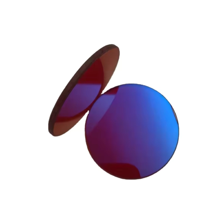
Thin Film Coating Deposition Technologies: Vendor Evaluation
Electron Beam (E-Beam) Evaporation
Electron Beam evaporation involves the thermal vaporization of source materials within a high-vacuum chamber using a focused electron beam. The vaporized material condenses onto the substrates positioned above the source. While highly cost-effective and compatible with a wide range of materials, this process is susceptible to nodule defects formed by source spitting. These nodules act as primary seeds for localized laser damage.
E-beam produces relatively porous, columnar films. These porous structures are susceptible to moisture absorption from the environment, leading to spectral shifting as the refractive index changes. It remains best suited for low-to-medium power, cost-sensitive applications where extreme environmental stability is not the primary concern.
Ion-Assisted Deposition (IAD / PIAD)
Ion-Assisted Deposition supplements the standard E-beam evaporation process with an energetic ion beam, typically Argon or Oxygen. As the evaporated molecules condense on the substrate, the ion beam bombards the growing film, compacting the layers. This results in a higher packing density and significantly better environmental stability compared to standard E-beam evaporation. IAD offers a strong middle ground, providing enhanced durability at a lower cost and faster cycle time than advanced sputtering processes.
Magnetron Sputtering (MS)
Magnetron Sputtering is a plasma-driven process where target materials are bombarded by energetic ions under strong magnetic fields. This ejects atoms from the target, which then deposit onto the substrate. The resulting films are highly uniform, dense, and amorphous.
This technology offers high deposition rates and exceptional repeatability over large substrate areas. Because the films are dense and non-porous, they exhibit near-zero humidity shift and high mechanical durability. This makes them highly suitable for high-power industrial laser systems operating in variable environments.
Ion Beam Sputtering (IBS)
Ion Beam Sputtering represents the pinnacle of thin film coating technology. High-energy ion beams bombard a target material, sputtering atoms with extremely high kinetic energy onto a rotating substrate. This process produces exceptionally dense, smooth, and virtually defect-free amorphous coatings.
IBS coatings exhibit near-zero scatter and absorption levels below 1 ppm. This technology is mandatory for ultrafast lasers, high-finesse optical cavities, and applications demanding extreme Laser-Induced Damage Thresholds. The primary trade-offs are the premium cost and significantly longer deposition cycle times.
| Deposition Technology | Film Density | Defect Level | Environmental Stability | Primary Application |
| E-Beam Evaporation | Low (Porous) | Moderate to High | Low (Spectral Shift) | Low-power optics |
| Ion-Assisted Deposition | Medium | Moderate | Medium | General purpose lasers |
| Magnetron Sputtering | High | Low | High | Industrial lasers |
| Ion Beam Sputtering | Very High | Extremely Low | Very High | Ultrafast lasers, extreme LIDT |
Critical Evaluation Dimensions for Specifying Laser Optics
Laser-Induced Damage Threshold (LIDT)
The Laser-Induced Damage Threshold is the maximum optical fluence or intensity that a coating can withstand before physical degradation occurs. This metric must be certified under strict ISO 21254 standards to ensure reliability. The mechanisms of damage vary drastically depending on the laser's operating regime.
In Continuous Wave or long-pulse regimes, damage is primarily driven by thermal absorption and the thermal transport properties of the coating-substrate boundary. Heat accumulation leads to melting or thermal stress fracturing. In short-pulse regimes, damage is dominated by defect-driven localized electronic breakdown. For ultrafast pulses, damage is governed by non-linear ionization mechanisms, such as multiphoton and avalanche ionization, which occur independently of classical manufacturing defects.
- Define the exact pulse duration, repetition rate, and beam diameter of your laser system.
- Specify the required LIDT value with a safety margin of at least 2x the operational fluence.
- Request vendor test reports that strictly adhere to ISO 21254 protocols.
- Verify that the testing was performed at the exact wavelength and angle of incidence required for your application.
Spectral Performance, Bandwidth, and AOI Sensitivity
Evaluating vendor capabilities requires scrutinizing their ability to deliver precise wavelength specificity. This ranges from single-wavelength optimization to complex dual-band or broad tunable spectral performance requirements. Angle of Incidence and polarization sensitivity are major factors. As the AOI increases, spectral transmission and reflection bands naturally shift toward the blue end of the spectrum. Furthermore, the performance profiles for p-polarization and s-polarization diverge significantly at high AOIs, requiring complex layer designs to maintain desired optical properties.
Group Delay Dispersion (GDD) Control
Ultrafast laser systems face a unique challenge regarding dispersion. Standard coatings possess inherent dispersion that distorts femtosecond laser pulses, stretching them in the time domain and drastically lowering their peak power. To combat this, laser optics designed for ultrafast applications utilize chirped and GDD-compensated mirrors. Evaluating a vendor involves assessing their ability to design and manufacture coatings with precisely variable layer thicknesses. These structures provide specific negative dispersion to compress the pulse or maintain short pulse durations throughout the optical path.
Advanced Metrology and Validation Techniques
Cavity Ring-Down Spectroscopy (CRDS)
Standard spectrophotometers cannot accurately measure reflectivity above 99.9%. Cavity Ring-Down Spectroscopy is applied to verify extreme reflectivity and quantify overall optical loss, which includes both absorption and scatter, in high-finesse mirrors. The mechanism involves injecting a laser pulse into a high-finesse optical cavity formed by the test optics. The system measures the decay rate of the light trapped within the cavity, providing a highly precise measurement of total cavity loss.
Photothermal Common-Path Interferometry (PCI)
Photothermal Common-Path Interferometry is utilized for directly measuring ultra-low absorption down to sub-ppm levels in both substrates and coatings. The mechanism utilizes a pump-probe laser configuration. A high-power pump laser locally heats the sample, inducing a slight change in the refractive index. A weaker probe beam passes through this heated region, and the resulting phase shifts are detected, allowing for the precise calculation of the absorption coefficient.
Spectrophotometry and Elipsometry
Spectrophotometry remains the standard for confirming spectral profiles, measuring transmission and reflection across wide wavelength bands. Ellipsometry is employed to determine the exact layer thicknesses and the complex refractive index profiles of the deposited films, ensuring the physical structure matches the theoretical design.
| Metrology Technique | Primary Measurement Parameter | Sensitivity Limit | Typical Use Case |
| Spectrophotometry | Transmission / Reflection | ~0.1% | Standard AR/HR verification |
| Ellipsometry | Layer Thickness / Refractive Index | Sub-nanometer | Process control, design validation |
| CRDS | Total Optical Loss (Scatter + Absorption) | < 1 ppm | Supermirrors, high-finesse cavities |
| PCI | Direct Absorption | Sub-ppm | High-power CW laser optics |
Implementation Risks and Mitigation Strategies
Stress-Induced Substrate Deformation
Thick, highly dense films, particularly those deposited via IBS, create significant physical stress. This compressive or tensile stress can warp the underlying substrate, distorting transmitted and reflected wavefronts and compromising critical peak-to-valley flatness specifications. To mitigate this risk, engineers must specify back-side compensation coatings that apply equal and opposite stress to the substrate. Furthermore, evaluating the vendor's metrology capabilities for measuring and correcting surface flatness post-deposition is essential.
Spectral Shift due to Thermal and Environmental Loading
Porous coatings absorb moisture from ambient humidity. Under vacuum conditions or during temperature fluctuations, this water desorbs, changing the effective refractive index of the layers and shifting the design wavelength out of the operational laser band. The primary mitigation strategy is to specify dense, non-porous deposition technologies like IBS or Magnetron Sputtering. Additionally, procurement teams should mandate thermal and humidity cycling tests compliant with ISO 9211-3 or MIL-C-48497A standards.
Contamination-Induced Degradation
Microscopic organic residues, dust, or volatile outgassing compounds can deposit onto the optical surfaces. Under intense laser illumination, these contaminants act as high-absorption centers, leading to rapid localized heating and catastrophic thermal failure. Mitigation requires enforcing strict cleanroom packaging protocols.
- Mandate Class 100 (ISO 5) cleanroom environments for all final inspection and packaging steps.
- Specify the use of non-outgassing optical storage containers.
- Establish approved solvent resistance standards for field cleaning.
- Implement strict handling procedures requiring powder-free finger cots or gloves.
Conclusion
- Match the deposition technology directly to your laser's power output and environmental operating conditions.
- Mandate ISO 21254 certified LIDT testing specific to your exact operating regime before approving any vendor lot.
- Require CRDS or PCI metrology data for any optic operating in high-finesse or high-power applications to verify low absorption.
- Specify back-side compensation coatings and environmental cycling tests to prevent substrate deformation and spectral drift during field deployment.
FAQ
Q: What is the difference between E-beam and IBS coatings?
A: E-beam evaporation uses thermal energy to vaporize materials, resulting in porous, less durable coatings susceptible to environmental shifts. Ion Beam Sputtering uses high-energy ions to deposit materials, creating extremely dense, defect-free, and environmentally stable coatings required for high-power and ultrafast lasers.
Q: Why does my laser optic degrade over time even below the LIDT?
A: Degradation below the specified Laser-Induced Damage Threshold is often caused by environmental contamination, moisture absorption in porous coatings, or thermal cycling stress. Microscopic dust or organic outgassing creates localized absorption centers that eventually cause thermal failure.
Q: How do you measure reflectivity above 99.9%?
A: Standard spectrophotometers lack the sensitivity for extreme reflectivity. Cavity Ring-Down Spectroscopy is used instead. It measures the decay time of a light pulse trapped between mirrors in a closed optical cavity to precisely calculate losses down to parts per million.
Q: What is Group Delay Dispersion in laser optics?
A: Group Delay Dispersion refers to the phenomenon where different wavelengths of light travel through a coating at slightly different speeds. In ultrafast lasers, this stretches the short pulse in time, significantly reducing its peak power. Specialized chirped mirrors compensate for this effect.
Q: Can optical coatings fix a warped substrate?
A: Coatings generally cause warping rather than fixing it due to internal compressive or tensile stress. However, applying a precisely engineered back-side compensation coating can balance the mechanical stress on the substrate, restoring the optic's required surface flatness.
Q: How does angle of incidence affect coating performance?
A: As the angle of incidence increases, the spectral transmission and reflection bands shift toward shorter wavelengths. Additionally, the coating's response to s-polarized and p-polarized light diverges, requiring specialized designs to maintain performance at high angles.
 English
 العربية
 Français
 Русский
 Español
 Português
 Deutsch
 italiano
 日本語
日本語 한국어
한국어 Nederlands
 Tiếng Việt
 ไทย
ไทย Polski
 Türkçe
 አማርኛ
አማርኛ ພາສາລາວ
 ភាសាខ្មែរ
 Bahasa Melayu
 ဗမာစာ
ဗမာစာ தமிழ்
தமிழ் Filipino
 Bahasa Indonesia
 magyar
 Română
 Čeština
 Монгол
 қазақ
қазақ Српски
 हिन्दी
 فارسی
فارسی Kiswahili
 Slovenčina
 Slovenščina
 Norsk
Norsk Svenska
 українська
 Ελληνικά
 Suomi
Suomi Հայերեն
 עברית
עברית Latine
 Dansk
Dansk اردو
اردو Shqip
Shqip বাংলা
বাংলা Hrvatski
 Afrikaans
 Gaeilge
 Eesti keel
 Māori
Māori


